Installation guide for commercial shutters
RSD Galvanised Steel Door Fitting Instructions
RSD Galvanised Steel Door Fitting Instructions
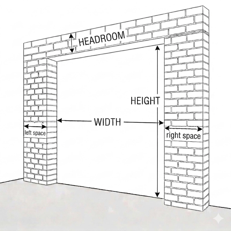
STEP 1. FIXING SUPPORTING STEEL WORK
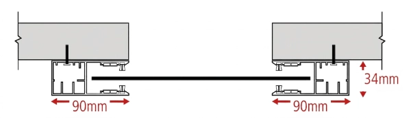
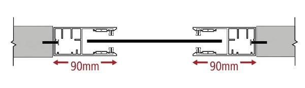
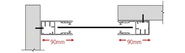
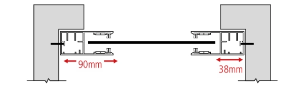
If your door is face fixing either externally or internally to obtain the correct distance between the two angle supports you need to measure the exact width of your door curtain without end locks, then 40mm or 50mm depending on your thickness of supporting angles, if you have angles which are 3mm thick then add 40mm or if your angles are 5mm thick add 50mm.
Example
if your lath cut size is 2100mm and your supporting steel work is 3mm thick then add 40mm, this will give you a back of angle size of 2140mm, this will give you enough air space for a smooth operation.
If you are using angles 5mm thick then please add 50mm, this will give you a back of angle size of 2150mm.
Securely fix your two angles or supporting steel work using suitable fixings (not supplied), these must be fitted plumb, parallel and level across the top of head plates.
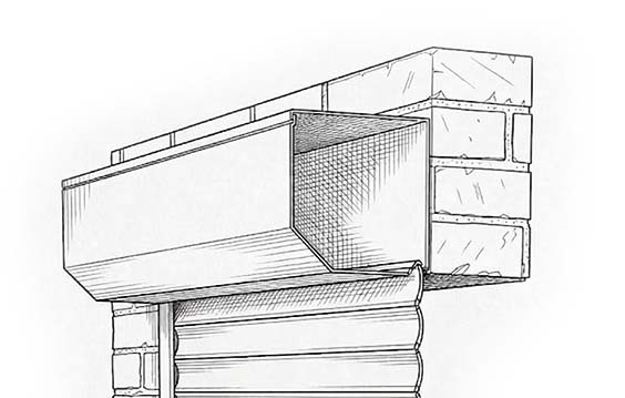
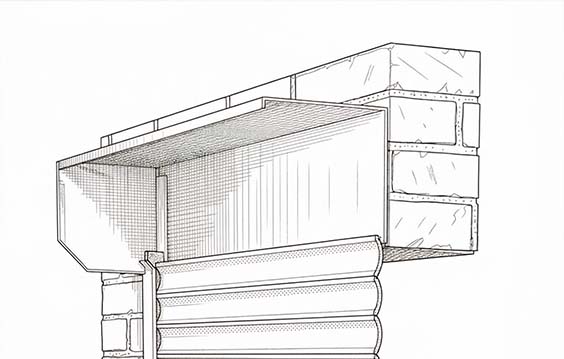
STEP 2. FITTING BARREL AND SAFETY BRAKE
Before lifting barrel assembly into place make sure you have fitted the safety brake onto either a 18mm square shaft or 30mm round shaft for larger safety brakes, on the 18mm square shaft there is a retaining screw and washer make sure this is fitted securely to prevent any lateral movement, larger safety brakes have a keyed shaft.
When lifting barrel assembly make sure you have the safety brake the correct way up, these are normally marked with top and have directional arrows pointing in which way the shutter descends, your motor end of the tube comes with different fittings so make sure you have the correct fitting before installation, smaller motors may have a star bracket fitting which is held in place with a split pin, some of the larger motors are bolted directly onto the head plates and held in place with 10mm nuts and bolts.
Small safety brakes are held in place with 4no. 6mm counter sunk screws and larger safety brakes have a foot plate with 2no. 10mm fixing points.
Please note that the 18mm square shaft may not be set at the correct size and you may need to extend the square shaft by undoing retaining screw and fastening back up once correct safety brake
is fitted.
Safety brakes are a maintenance free unit and must be inspected every six-month depending on usage, the roller shutter door company is not responsible for any damage caused by wrong installation or improper use.
STEP 3. WIRING THE MOTOR
All electrical work must be carried out by a trained or qualified electrician in accordance with enclosed motor and control panel instructions.
Please clip the cable away from any moving parts and follow the instructions for your control unit.
Once the motor has power, start the barrel to turn in a downward direction until it stops and this should be your bottom limit, leave in this position until you have installed the rest of the door.
STEP 4. FITTING THE LATH
Please isolate the power before commencing.
Your lath should come in bundles of 8 or 10 depending on the size of your door, you should have a section marked up top and one marked bottom, your first segment will be marked top and this will have some smaller segments with either 8mm or 10mm holes drilled for locating onto your barrel assembly. Make sure you have the barrel assembly bolts facing you before lifting into place as this will make the job a lot easier.
Your lath should always run around the tube from the back of the head plates and once secured in place you can start to add on more lath, this is done by opening the quirk which is covered by an endcap which can be moved so you can laterally slide you next segment together until you have installed all the lath.
STEP 5. FITTING GUIDE CHANNELS
Once the curtain is securely in position you can operate the door to an open position making sure that the door does not roll over the top of itself, once the curtain is in the open position you can now fit your guide channels making sure that the guides are facing the correct way and fix in place with counter sunk screws provided.
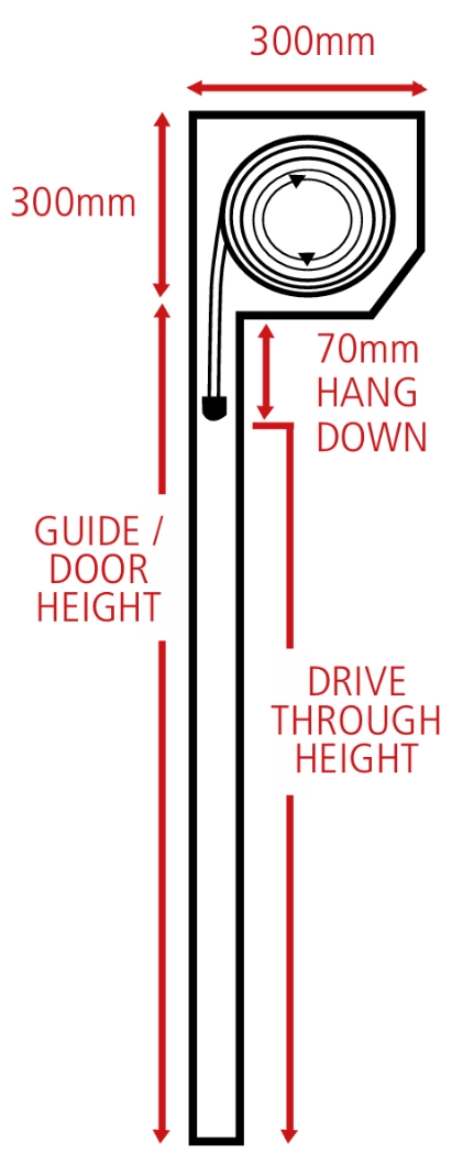
STEP 6. SETTING THE LIMITS
You have two limit adjustment screws on the head of the motor, refer to instructions supplied with your purchase. These are your adjustment screws for making the door open and close, using the limit adjustment tool supplied with your door turn either adjustment screw to + to make the door travels further and use the – adjustment if the door is over running, make sure that you have 50mm to 70mm of you bottom bar in the guide channels when your door is in the open position and your roller shutter is firmly closed on the ground.